
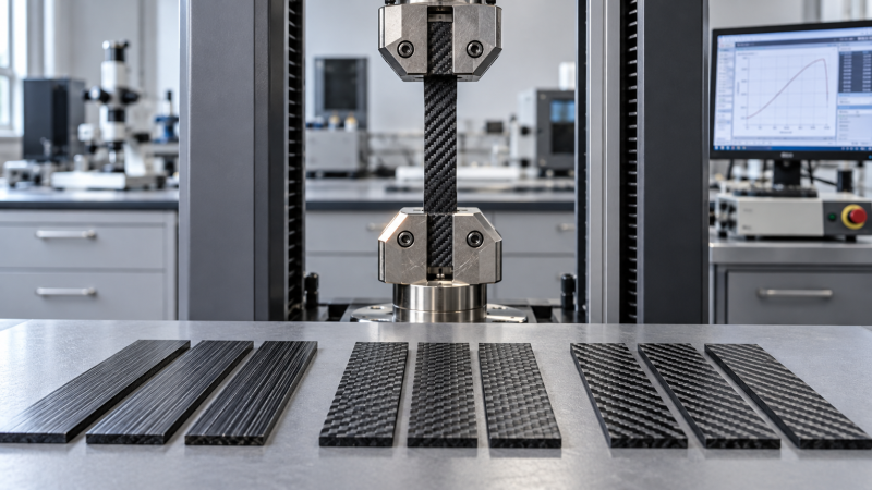
Two specimens made from the same carbon fiber composite can produce markedly different test results when their fibers face different loading directions during mechanical testing.
For quality control and safety teams, that difference can affect material acceptance, failure analysis, and confidence in automotive component performance under demanding service conditions.
In automotive composite testing, fiber orientation influences measured stiffness, strength, and failure modes, making specimen alignment and laminate layup essential context for interpreting laboratory results.
The practical rule is straightforward: compare results only after confirming equivalent orientation, specimen location, conditioning, and test methods, then investigate differences against approved acceptance criteria.
Why can the same composite pass one test and fail another?
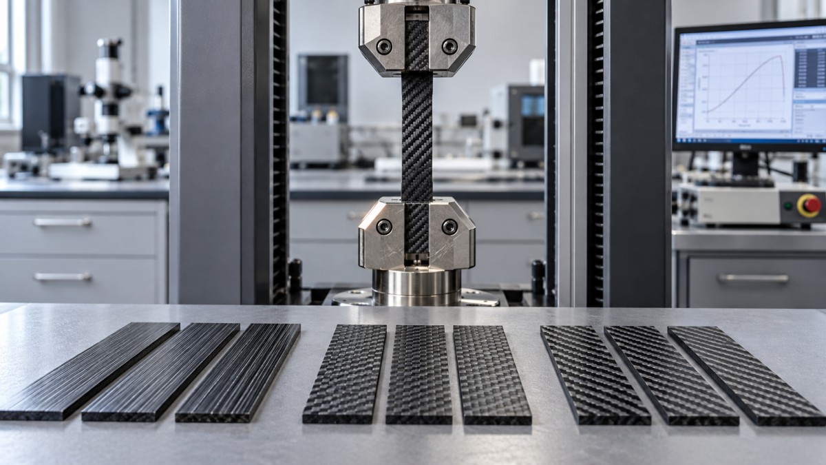
Continuous fibers reinforce composites most effectively along their length. Loading across those fibers places greater demands on the resin and the interface between constituent materials.
Consequently, longitudinal, transverse, and off-axis specimens measure different responses. A lower transverse strength does not automatically indicate defective material or an unstable manufacturing process.
For a unidirectional ply, 0° normally means fibers parallel to a defined reference direction. That reference must be stated before test results can be interpreted.
A specimen cut at 0° to a component datum may still contain several ply angles. Coupon direction and individual ply orientation describe different information entirely.
Likewise, a balanced laminate containing equal positive and negative angles can behave differently from a unidirectional laminate, even when both use identical fibers and resin.
Quality decisions therefore need orientation-specific limits. Applying a longitudinal strength requirement to transverse coupons can reject acceptable material while obscuring the actual cause of disagreement.
Conversely, testing only the strongest direction can overlook weaknesses relevant to mounting points, side impacts, or local load paths where forces cross the main reinforcement.
The first investigation question should be whether the test represents the specified material direction and service concern. Only then should teams assess manufacturing quality or supplier consistency.
Which mechanical test results change most with fiber direction?
Orientation affects nearly every mechanical property, but the controlling mechanism changes with the loading mode. Interpreting the measured value requires understanding what actually failed first.
In tension, a longitudinal coupon may fail through fiber fracture, while a transverse coupon may fail through matrix cracking or interface separation at lower stress.
Compression introduces additional sensitivity to fiber misalignment and waviness. Premature failure may reflect genuine material defects, specimen instability, or fixture effects that require separate investigation.
Flexural results combine tensile, compressive, and shear responses. Changing the surface ply direction can change the result even when overall laminate composition remains the same.
For suitable continuous-fiber laminates, ±45° tensile testing can characterize in-plane shear response using ASTM D3518. Interpretation must account for the method’s assumptions and strain limits.
Impact resistance cannot be ranked reliably from fiber direction alone. Resin toughness, ply thickness, stacking sequence, thickness, and impact conditions also influence the resulting damage.
A laminate with favorable impact energy absorption may still retain insufficient strength afterward. Safety assessments should connect impact damage to the component’s required residual performance.
Why ply angles alone do not describe the laminate
Two laminates can contain identical percentages of 0°, 90°, and ±45° plies yet deliver different bending, damage, or interlaminar behavior because their stacking sequences differ.
Plies farther from the laminate midplane contribute more strongly to bending stiffness. Moving longitudinal plies toward the surfaces therefore changes flexural response without changing composition.
Symmetry and balance also matter. Unsymmetric laminates can exhibit extension–bending coupling, while unbalanced angle arrangements can introduce coupling between normal loading and in-plane shear deformation.
Even laminates described as quasi-isotropic need careful interpretation. Their approximately direction-independent in-plane elastic behavior does not establish equal strength, impact resistance, or through-thickness performance everywhere.
Woven reinforcements add yarn crimp and architecture effects. Warp and weft directions should remain identifiable, particularly when yarn properties or fabric construction differ between directions.
For chopped-fiber molded parts, orientation is a local distribution rather than a single ply angle. Flow, gates, ribs, and weld lines influence the reinforcement pattern.
A coupon taken near a gate may therefore differ from one taken across a weld line. Sampling location becomes part of the material description itself.
How can teams distinguish orientation effects from testing errors?
When results move unexpectedly, verify traceability before changing the material specification. Small documentation errors can create apparent performance shifts that resemble a process quality problem.
Start with the drawing reference, panel markings, cutting plan, and specimen labels. Confirm that the laboratory’s loading axis matches the orientation requested by the engineer.
Next, review specimen dimensions, edge quality, tabs, fixture setup, and strain measurement. Machining damage or misalignment can change failure behavior independently of the intended orientation.
Off-axis coupons may develop shear deformation and strain fields that interact with grip constraints. Unexpected failures near grips deserve investigation before results support material acceptance.
Digital image correlation can help reveal nonuniform deformation, provided calibration and analysis are appropriate. It supports diagnosis but does not replace applicable test validity criteria.
Review conditioning and test temperature alongside alignment. Moisture and elevated temperature can particularly affect matrix-dominated responses, complicating comparisons between longitudinal and transverse test results significantly.
Finally, compare failure locations and fracture descriptions with the chosen method. An invalid failure should trigger documented review, rather than automatic classification as a material defect.
What should an orientation-aware test plan include?
Begin with the component’s credible load cases, including installation loads, repeated service loading, impact, and environmental exposure. Select coupon directions that address those specific concerns.
For continuous-fiber materials, testing longitudinal, transverse, and relevant off-axis directions can separate fiber-dominated and matrix-dominated behavior. The required coverage depends on the design and qualification basis.
For molded discontinuous-fiber components, define extraction locations relative to flow and geometry. Include structurally important regions where orientation changes or weld lines could affect performance.
Use methods suited to the material and property. ASTM D3039 addresses tensile properties of polymer matrix composites, while ASTM D6641 covers compression using combined loading.
ASTM D7264 addresses flexural properties. ISO 527-4 and ISO 527-5 provide tensile frameworks for specified composite types; select the applicable standard and agreed edition explicitly.
These methods define testing procedures, not universal automotive acceptance limits. Requirements must come from the approved specification, customer agreement, or validated engineering qualification program itself.
For every test group, retain orientation, complete layup, batch identity, sampling location, specimen dimensions, conditioning, loading rate, fixture details, and observed failure mode with results.
Choose replication based on the governing specification and decision risk. A few successful coupons cannot establish a reliable lower-bound property for every production condition encountered.
How should quality teams compare suppliers and production lots?
Supplier comparisons are meaningful only when test conditions and material descriptions align. A higher published strength may simply reflect a more favorable direction or laminate.
Request the reinforcement form, fiber volume fraction, resin system, cure condition, layup, and test standard. These details often explain differences that summary datasheets leave unresolved.
Compare distributions as well as averages. Report sample count, scatter, and failure modes so a strong mean does not conceal inconsistent processing or weak specimens.
Keep routine control limits separate from engineering acceptance limits. Control charts detect process shifts, while acceptance decisions determine whether specified requirements have actually been satisfied.
For example, if longitudinal strength remains stable while transverse strength declines, investigate matrix cure, interfaces, conditioning, and defects before assuming the fiber grade has changed.
If several directional properties shift together, review broader process variables, measurement practices, and material identity. Such patterns guide investigation but do not establish root cause alone.
Agree on a documented retest process before disputes arise. Define invalid-test handling, additional sampling, retained material review, and the authority responsible for final lot disposition.
What do coupon results establish about vehicle safety?
Coupons provide controlled measurements of selected material responses. Components introduce curvature, holes, joints, thickness transitions, and manufacturing variations that can alter local stresses and failure mechanisms.
A strong longitudinal coupon does not establish crashworthiness. Crash response depends on geometry, progressive crushing, strain rate, load introduction, and how damage develops throughout the structure.
Fatigue performance also needs relevant directional evidence. Repeated loading can accumulate matrix cracks and delamination before a component reaches the static strength measured during qualification.
Likewise, an orientation predicted to improve stiffness may change crushing behavior or joint loads. Design changes need evaluation against the complete set of safety requirements.
Use a staged validation approach linking material coupons, representative features, subcomponents, and component tests. Each stage should resolve uncertainties that simpler specimens cannot adequately represent.
Where simulations use directional material properties, verify the orientation mapping and applicable failure model. Matching one coupon curve does not validate predictions across all loading conditions.
For safety-critical decisions, maintain traceability from the tested material and layup to the manufactured component. Record approved deviations and the evidence supporting their acceptance explicitly.
Making reliable acceptance decisions
Fiber orientation determines which reinforcement mechanisms a test activates. Reliable automotive composite testing therefore begins with a defined direction, representative sampling, and a documented laminate description.
Before accepting or rejecting material, confirm that the specimen, method, environment, and failure mode support the intended comparison. Investigate unexplained differences using traceable evidence first.
Quality and safety teams gain the most useful evidence when directional coupon data connects to actual component loads, manufacturing variability, and the approved acceptance criteria.
The decisive question is whether the tested orientation demonstrates the performance required at the relevant location. That connection turns laboratory measurements into defensible quality decisions.