
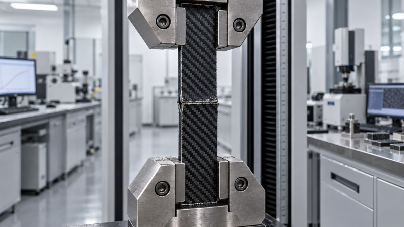
Automotive composite materials testing for CFRTP weld strength
A CFRTP weld can look sound yet contain interfacial defects that compromise joint strength under service loads. Visual inspection alone cannot establish structural acceptance.
For quality control and safety teams, automotive composite materials testing must connect mechanical performance, internal defect detection, environmental durability, and evidence that production remains controlled.
The practical objective is to demonstrate adequate joint performance across expected manufacturing variation and service conditions, using acceptance criteria linked to the component’s safety requirements.
This article explains how to select complementary tests, interpret failure evidence, and establish release controls for carbon fiber-reinforced thermoplastic welds in lightweight vehicle structures.
What evidence makes a CFRTP weld acceptable?
A defensible acceptance decision combines three elements: sufficient mechanical capacity, an acceptable defect population, and a qualified welding process operating within its validated production limits.
No universal weld-strength threshold applies across CFRTP components. Required performance depends on joint geometry, laminate architecture, load direction, temperature, exposure history, and structural load paths.
Begin with the component’s credible failure scenarios. A bracket under repeated vibration needs different evidence from an enclosure joint carrying crash-related loads or sealing requirements.
Translate those scenarios into measurable requirements before choosing laboratory methods. Specify relevant load cases, allowable deformation, durability targets, and consequences if a weld partially separates.
Distinguish qualification from routine release. Qualification establishes performance over a defined operating envelope; production controls determine whether manufactured joints remain consistent with that qualified condition.
Safety teams should also identify whether neighboring fasteners, bonded regions, or redundant load paths remain effective after local weld damage, where the design requires redundancy.
The resulting acceptance plan should state which measurements release a part, which trigger investigation, and which require rejection or a formally qualified repair procedure.
Which welding variables should quality teams control?
CFRTP welding joins compatible thermoplastic matrices through heating, intimate contact, and polymer interdiffusion. Strength therefore depends on the complete thermal and pressure history during joining.
Insufficient heating can leave incomplete fusion. Excessive heating can degrade the matrix, disturb fibers, or create porosity, even when the external weld surface appears satisfactory.
Joining pressure and consolidation time influence contact and void closure. Excessive pressure can squeeze out resin or change local thickness, affecting the final joint geometry.
Cooling history also matters. For semicrystalline matrices, crystallinity and residual stresses can change with cooling conditions, influencing stiffness, toughness, dimensional stability, and subsequent service behavior.
Record material grade, reinforcement architecture, laminate thickness, fiber orientation, moisture conditioning, surface preparation, and overlap geometry. Similar-looking carbon fiber laminates can produce substantially different results.
Capture method-specific variables as well: ultrasonic amplitude and displacement, resistance-welding current and heating-element configuration, or induction power, travel speed, and coil position as applicable.
Machine energy or power readings are process indicators; their relationship to interface temperature and final weld performance must be demonstrated for the actual material and geometry.
How should weld strength be measured and reported?
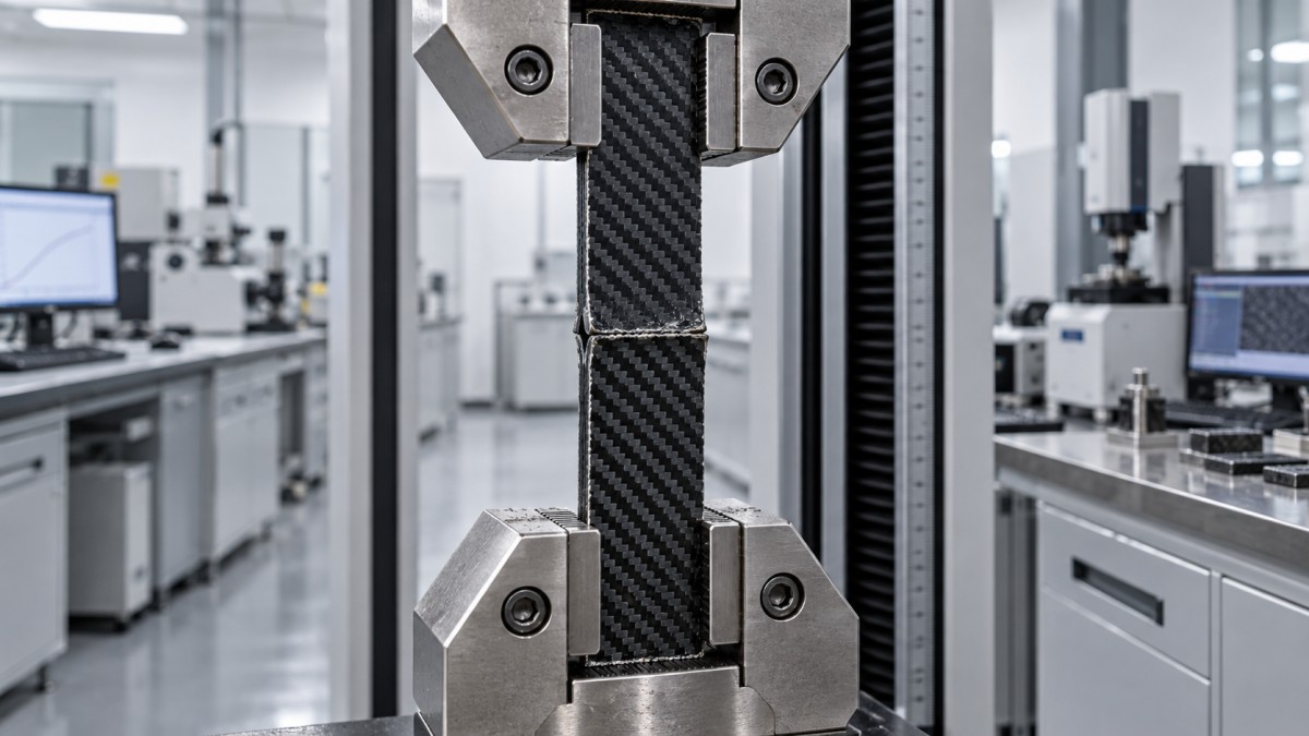
Lap-shear testing is often a useful starting point because it compares joints efficiently. However, eccentric loading introduces bending and peel stresses alongside nominal shear loading.
Report apparent lap-shear strength as maximum force divided by the defined overlap area. State that area explicitly, including how incomplete weld coverage is treated.
Also retain maximum load, displacement, specimen dimensions, loading rate, conditioning, and failure location. A single normalized strength value can conceal important differences between joint designs.
ASTM D5868 addresses adhesive lap-shear testing of fiber-reinforced plastic joints. It may inform specimen planning, but a welded adaptation requires explicit documentation and technical justification.
Confirm the current scope of any selected standard. Using a familiar specimen shape does not establish that a welded joint complies with an adhesive-joint standard.
Add peel-sensitive or opening-load tests when service loading can separate the overlap edges. Strong lap-shear results alone cannot establish resistance to those failure modes.
Use component or subcomponent tests to check representative constraints, curvature, thickness transitions, and load introduction. Coupon performance cannot fully reproduce the stress distribution of an assembly.
What do fracture surfaces and result variation reveal?
Inspect both fracture surfaces after destructive testing. Separate interface failure, matrix tearing, laminate delamination, fiber damage, and mixed failure, using photographs and consistent classification rules.
Failure outside the weld may indicate that another region governed the test. It does not establish unlimited weld capacity or guarantee performance under different loading.
Likewise, a high peak load followed by sudden separation may be unsuitable where damage tolerance matters. Examine the force-displacement response and available deformation before failure.
Compare failure modes alongside numerical results when optimizing welding conditions. An apparent strength improvement may shift damage into the parent laminate without improving overall structural reliability.
Evaluate variation across independent welds, material lots, operators, equipment setups, and relevant production periods. Multiple coupons cut from one panel provide limited evidence of process reproducibility.
Set sample sizes and statistical methods according to risk and the qualification objective. Report scatter and justified lower performance bounds, rather than relying exclusively on averages.
Investigate unexpectedly weak specimens before excluding them. A low result caused by a realistic production defect may be more decision-relevant than the average qualification value.
Which hidden defects can nondestructive inspection detect?
Ultrasonic inspection can identify some voids, delaminations, and incomplete joining regions. Detectability depends on laminate attenuation, fiber architecture, thickness, interface geometry, and access to the joint.
Active thermography can screen suitable geometries for thermal-response differences associated with defects. Inspection depth, heating uniformity, surface condition, and measurement timing influence the results substantially.
X-ray computed tomography can support development investigations into internal geometry and porosity. Resolution, component dimensions, carbon-polymer contrast, and inspection time constrain its production use.
No inspection method directly converts every signal into weld strength. Intimate-contact interfaces with weak bonding can be especially difficult to distinguish from adequately fused material.
Validate inspection performance using representative reference specimens and destructive correlation. Include realistic defect types, locations, and sizes rather than relying solely on convenient artificial reflectors.
Where required by risk, establish detection reliability and measurement repeatability. Account for operator effects, equipment settings, surface access, and the smallest structurally relevant defect.
Use nondestructive inspection to support defined acceptance decisions. A clean scan is meaningful only within the demonstrated detection capability and the component’s qualified defect limits.
Will the weld remain strong through vehicle service?
Room-temperature static testing provides an initial comparison, but vehicle joints experience changing temperatures, moisture, chemicals, vibration, and sustained loads that can alter their performance.
Select conditioning from the installation environment. Relevant exposures may include humidity, water immersion, thermal cycling, road salt, cleaning agents, and application-specific automotive fluids or electrolytes.
Test at relevant service temperatures when possible. Measuring only after specimens return to room temperature can miss reversible softening or stiffness loss during hot operation.
Moisture conditioning should reflect the matrix and specimen dimensions. Document exposure time, temperature, mass change where useful, and whether the chosen condition approached moisture equilibrium.
Fatigue testing should reproduce meaningful load ratios, amplitudes, frequencies, and environmental conditions. Monitor specimen temperature because accelerated cycling can introduce self-heating and distort the comparison.
Assess creep or sustained-load deformation when the joint carries persistent loads. For crash-relevant structures, use appropriate dynamic tests because quasi-static strength alone cannot establish impact performance.
Compare aged performance against the design requirement and unaged baseline. Percentage strength retention is useful, but a high retention percentage cannot compensate for inadequate absolute capacity.
How can qualification become a practical production control plan?
Develop a process window by testing meaningful combinations of heating, pressure, joining time, and cooling conditions. Include interactions and credible boundary conditions for production equipment.
Challenge the window with expected variation in incoming material, laminate thickness, moisture, alignment, and tooling contact. Nominal settings alone provide insufficient evidence of production robustness.
Connect each critical variable to a monitoring method, limit, record, and response. Record actual process traces where practical, including sensor calibration and equipment maintenance status.
Define the relationship between witness coupons and actual parts. Different heat flow, restraint, or geometry can make a convenient coupon unrepresentative of the production joint.
Combine appropriate process monitoring, inspection, and periodic destructive verification. Their frequency should reflect defect consequences, demonstrated process capability, and the ability to contain affected production.
Statistical control limits describe process behavior; specification limits express requirements. A stable process can still produce unacceptable joints if its performance does not meet specifications.
Establish change-control triggers for resin grade, fiber sizing, laminate supplier, heating elements, tooling, software, and equipment relocation. Assess each change against the qualified process evidence.
What should trigger containment, investigation, or rejection?
Acceptance rules should distinguish confirmed nonconformance from uncertain evidence. An out-of-limit welding trace, unexpected inspection indication, or destructive-test failure requires a predefined response and disposition.
Identify potentially affected parts through traceability records. Preserve links between material batches, equipment, timestamps, process settings, inspection results, and any subsequent repair or retest activity.
Define containment boundaries using evidence about when the process changed and recovered. Passing a few later samples does not automatically establish that earlier production was acceptable.
For ambiguous inspection results, use a qualified secondary method or engineering review. Repeated scanning without defined interpretation rules can create inconsistent decisions and obscure real defects.
Repair welding requires its own technical justification because reheating can alter local consolidation, crystallinity, residual stresses, or laminate condition. Verify repaired performance against applicable requirements.
Supplier submissions should include specimen geometry, conditioning, individual results, failure photographs, inspection capability, and process traceability. A headline strength value provides too little context for approval.
For procurement and safety reviews, prioritize evidence from the proposed material, welding process, and component geometry. Results from another polymer or laminate require a justified transfer assessment.
Build acceptance around demonstrated structural performance
Effective automotive composite materials testing connects service requirements to mechanical results, failure mechanisms, inspection capability, and controlled manufacturing records. Each evidence source addresses a different uncertainty.
Release CFRTP welds against documented requirements supported by representative qualification. Include environmental and cyclic loading where relevant, and use component testing to confirm critical assumptions.
For quality and safety teams, the decisive question is whether the available evidence supports reliable performance throughout the intended operating envelope, including credible manufacturing variation.
A visually clean weld is only the starting observation. Confidence comes from validated tests, understood limitations, traceable production controls, and clear actions when evidence falls outside acceptance criteria.